|
|
This chapter presents a second case study of role-model-based
framework design. It describes the Tools framework of the KMU
Desktop project (KMU = "Kleinere und Mittlere Unternehmen",
a Swiss-German abbreviation for small and medium-size enterprises).
The KMU Desktop project develops a system to support the corporate
customer credit process of UBS AG, a large international bank.
A first version of the Tools framework was designed and implemented
using a traditional class-based approach. After about a year of
use, a redesign was carried out using role modeling and the role-model-based
patterns catalog as an aid. The chapter presents both designs
as well as the redesign team's experiences during the redesign
process. Also, the chapter compares the two designs and analyzes
how role modeling helped to reach the much cleaner redesign.
7.1 Case study overview
UBS AG is a large bank, currently (mid 1999) the largest bank
in the world with respect to assets under management. The KMU
desktop system is an interactive software system that supports
the credit management of UBS for small and medium-size corporate
customers. Credit officers use it to determine whether a credit
is to be granted, to assess and control its risk, and as a support
of the whole granting and reviewing process.
7.1.1 Project history
The corporate customer division of UBS has undergone major
changes in recent years, and new software was to reflect these
changes and to help account managers and credit officers work
more effectively. The KMU Desktop project's mission was to develop
this new software support. The project's primary focus was to
support credit management of small and medium-size corporate customers
of UBS.
The project's approach to analysis, design and implementation
is based on the Tools and Materials metaphor [RZ95, RZ96]. Applications
are implemented using Smalltalk on Windows-based PC clients, C++
on Solaris servers, and CORBA as middleware. The overall architecture
is a three-tier client/server architecture. The design approach
is based on frameworks.
7.1.2 The case study
A particularly important framework is the Tools framework.
It is used to develop client-side software tools, which account
managers and credit officers use in their daily work. A first
version of this framework was developed in-house and finished
in April 1997. The framework contributed significantly to an increase
in productivity, but it was also difficult to use. Framework users
had problems understanding and properly using it. After about
one year of, project management decided to redesign the framework
to overcome the existing problems with using it.
In March 1998, a team of three developers carried out the redesign.
This redesign team consisted of two of the original developers,
Gregory Hutchinson and Birgit Rieder, and me. The redesign team
first analyzed the existing framework, determined its functionality
and the problems developers had using it, described this functionality
using role models, added new functionality and changed existing
one, and recomposed the pieces to arrive at a new framework design.
In the following, the word "team" refers to the redesign
team mentioned above. "Framework developer" refers to
either Gregory Hutchinson or Birgit Rieder, or both. "Framework
user", or user for short, refers to other developers from
the KMU Desktop project that are using the Tools framework to
build software tools.
7.1.3 Chapter structure
First, this chapter presents the original framework. The framework
is described using the original class-based documentation available
to framework users. We add to this description what I learned
from my colleagues from the redesign team. This discussion includes
the problems framework users had using the framework.
Then, the chapter describes the new revised framework using
role modeling. The framework structure changed in many important
aspects, but still, one can recognize the original framework and
its intent. The role-model-based description makes use of design
patterns terminology, based on the catalog of role model patterns
[Rie97a]. An abbreviated form of this catalog is available as
Appendix D.
Finally, the experiences of the redesign team with the redesign
process and the experiences of users of the new framework are
presented and analyzed.
7.2 The original Tools framework
This section presents the original Tools framework, as described
by its developers. The original design had been carried out using
traditional class-based modeling. In addition, Smalltalk method
categories had been used to structure the class interfaces. Also,
the developers had used design patterns occasionally. However,
they had not used role modeling.
7.2.1 Framework overview
The Tools framework is a framework used to build software tools
for interactive software systems based on the Tools and Materials
Metaphor [RZ95, RZ96]. It is a white-box framework.
Software system users use tools to change an underlying domain
model called the materials (of work). Examples of tools are form
editors. Form editors work on forms, their material. Other examples
of tools are customer browsers, which serve to browse a list of
customers, and risk assessment tools, which serve to determine
the risk of a loan (current or applied for by a customer).
7.2.1.1 Software tools
A software tool is built from a hierarchy of tool components.
Every tool component represents a specific part of the overall
tool's functionality. Every tool component provides both a user
interface and the functionality behind it to access and manipulate
parts of the underlying domain model. At any one time, users interact
with one tool component from the hierarchy. The tool component
carries out user requests. Such a user request might cause complex
control flow within the tool component hierarchy, possibly involving
all components up to the root component of the hierarchy.
A tool component consists of at least two objects: one functional
part object (FP object) that represents the functionality of the
tool component, and one or more interaction part objects (IP objects)
that provide the user interface to use the tool component's functionality.
Thus, a tool component does not manifest itself as a single object,
but rather as one or more IP objects with one FP object. When
speaking of a tool component, typically the component's FP object
is meant that represents the component.
A software tool is represented to its environment by the FP
object of the root tool component, the so-called root-FP object.
The tool component hierarchy may be arbitrarily deep. In practice,
it seldom goes beyond three levels. The root-FP object manages
the overall tool. Every tool component is responsible for managing
its subordinate components (sub-components). In the component
hierarchy, every FP object receives two types of information from
sub-components. First, an FP object receives user requests from
sub-components that could not be handled. Second, an FP object
receives notifications about state changes from sub-components
based on successfully executed user requests. The overall structure
follows the Bureaucracy pattern [Rie98].
As an example, consider a simple NoteBrowser tool. It consists
of one root tool component, the NoteBrowser tool component, and
two subordinate NoteLister and NoteEditor tool components. The
NoteLister component presents a list of notes to choose from,
and the NoteEditor component lets users edit a note selected in
the NoteLister. The object structure of the tool is depicted in
Figure 7-1.
The object pair (noteBrowserIP, noteBrowserFP) from Figure
7-1 forms the root tool component, and the object pairs (noteListerIP,
noteListerFP) and (noteEditorIP, noteEditorFP) form the two sub
tool components.
Figure 7-2 depicts the original Tools framework, as taken from
the documentation. A number of minor adjustments were made, mainly
to make the design more readable and to correct omissions. Also,
the class names have been translated to English where necessary.
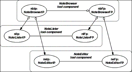
- Figure 7-1: Example object structure of a simple NoteBrowser
tool (the gray boxes are a visual aid to mark the extent of a
tool component).
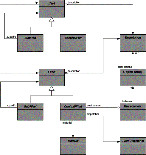
- Figure 7-2: The KMU Desktop Tools framework.
The framework classes for tool construction comprise the interaction
part classes IPart, SubIPart, and ContextIPart, as well as the
functional part classes FPart, SubFPart, and ContextFPart. The
framework context comprises the classes Material, Environment,
EventDispatcher, ObjectFactory, and Description.
As discussed, a tool component comprises one FP object (functional
part object, FPart instance), and one or more IP objects (interaction
part objects, IPart instances). An FP object must always be an
instance of a concrete subclass of FPart, and an IP object must
always be an instance of a concrete subclass of IPart.
ContextFPart is the superclass of all root-FPart classes, so
if an FP object is to be the root object of the FP object hierarchy,
its must be an instance of (a subclass of) ContextFPart. Similarly,
a root-IP object must be an instance of (a subclass of) ContextIPart.
Also, an FP object that is an object in the FP hierarchy, but
that is not the root-FP object, must be an instance of (a subclass
of) SubFPart. Similarly, an IP object that is an object in the
IP hierarchy, but that is not the root IP object, must be an instance
of (a subclass of) SubIPart.
In the NoteBrowser tool example, NoteBrowserFP and NoteBrowserIP
are subclasses of ContextFPart and ContextIPart, respectively,
and NoteListerFP and NoteListerIP, and NoteEditorFP and NoteEditorIP
are subclasses of SubFPart and SubIPart respectively.
7.2.1.2 Environment integration
An environment object, the sole instance of the Environment
class, manages software tools. The root-FP object represents a
tool; it is an instance of a subclass of ContextFPart. Thus, ContextFPart
defines the interface through which the environment communicates
with a tool.
The environment object receives requests for tool creation
from a desktop (not shown in a figure). The request provides a
name for the tool (a string), but not the tool nor its class.
The environment uses tool specifications and the object factory
to map the name onto a tool class and to instantiate the tool
class. The tool class must be a concrete subclass of ContextFPart.
Tool specifications are instances of class Description, and the
object factory is the sole instance of class ObjectFactory.
The process of determining a tool class from a specification
is described by the Product Trader pattern [BR98]. A description
object can calculate a key from the parameters it originally received
from a client (an example of a key is the tool name string). The
key identifies the tool class. It is typically unique. For each
description, the object factory determines the corresponding class,
either by looking it up in pre-configured tables, or by walking
over the class hierarchy matching each class with the key.
Once the root-FP object has been instantiated, the environment
object properly initializes the tool. First, it repeats the object
creation process for the root-IP object. This time, the key is
the root-FP class itself. Using the object factory guarantees
that the correct root-IP for the given root-FP is created, while
it need not to hard-coded which IP class matches which FP class.
Also, the environment object provides a new tool with parameters
from the desktop, most notably the material the tool is to be
used on (if specified by the user).
More handling is going on behind the scenes, in particular
on the desktop and for loading and storing materials, before tools
can handle them. However, this part of the overall application
framework does not add much to the discussion of the Tools framework
and is therefore omitted.
7.2.2 Classes and their functionality
The classes of the framework can be categorized as follows:
- FPart hierarchy. These are the FPart, SubFPart, and ContextFPart
classes.
- IPart hierarchy. These are the IPart, SubIPart, and ContextIPart
classes.
- Tools environment. These are the Environment, EventDispatcher,
Description, and ObjectFactory classes.
The following first part describes the FPart class hierarchy.
- FPart is the abstract superclass for all FP objects. It defines
the functionality common to all of them. Specific FP classes
must inherit from it. FPart defines the following protocols:
- Event notification. Clients of an FP object can register
to be notified about events. A client registers for specific
event types and provides the FP with operation names to call
if the event occurs. By providing different operations for each
event type rather than a dedicated callback operation, no common
protocol is needed among observers that are interested in different
event types.
- Request handling. An FP provides operations to receive requests
from its sub-FP objects. Requests are instances of a dedicated
Request class.
- Sub-FP instantiation. An FP declares operations to instantiate
its sub-FP object. These are internal operations to be implemented
by subclasses (inheritance protocol).
- FPart description. An FP class provides a description of
its properties. In Smalltalk, this is a class-level operation.
The description provided is an instance of class Description.
The description is used in the instantiation of objects through
the object factory (see below).
- IPart instantiation. An FP provides operations to instantiate
its IP (there is exactly one IP object for an FP object in this
Tools framework).
- ContextFPart is the abstract superclass of all root-FP classes.
Every tool must define a subclass of ContextFPart whose instances
represent the tool to the environment. ContextFPart inherits
from FPart and adds the following protocols:
- Event dispatcher connection. A root-FP provides operations
to connect to the event dispatcher. It knows its dispatcher,
forwards specific events to it, and receives events from it.
- Environment connection. A root-FP provides operations to
connect to its environment. A client may ask about the current
tool status, for example whether it has been launched successfully.
- Material handling. A root-FP provides operations to provide
sub-FP objects with the current material.
- SubFPart is the abstract superclass of any FP class of objects
from the FP hierarchy, except for the root-FP object, which must
be an instance of a subclass of ContextFPart. SubFPart is a subclass
of FPart and adds the following protocols:
- Super-FP handling. It provides operations to get and set
the super-FP.
The following second part describes the IPart class hierarchy.
- IPart is the abstract superclass of all IP objects. It defines
the functionality common to all IP objects. Every IP class must
inherit from it to extend the framework. IPart defines the following
protocols:
- FPart handling. An IP object provides operations to attach
itself to an FP. It receives the FP object and registers with
it for the event types it is interested in.
- Sub-IP instantiation. An IP declares operations to instantiate
its sub-IPs. These are internal operations to be implemented
by subclasses (inheritance protocol).
- IPart description. An IP class provides a description of
its properties. In Smalltalk, this is a class-level operation.
The description provided is an instance of class Description.
It is used in the instantiation of IP objects through the object
factory (see below).
- ContextIPart is the abstract superclass of all root-IP classes.
Every new tool must define a subclass of ContextIPart. ContextIPart
inherits from IPart and adds the following protocol:
- GUI handling. A root-IP provides operations to retrieve an
icon, which represents the tool on the desktop. It also provides
operations to open and close the main window.
- SubIPart is the abstract superclass of any IP class of objects
from the IP hierarchy, except for the root-IP object, which must
be an instance of a subclass of ContextIPart. SubIPart is a subclass
of IPart, to which it adds the following protocols:
- Super-IP handling. It provides operations to get and set
the super-IP.
Both SubFPart and SubIPart leave open the handling of further
embedded sub-parts. This functionality must be defined and implemented
by every sub-part anew, as described by the section on how to
use the framework.
Finally, the following third part describes the environment
classes.
- Environment is a concrete class, whose sole instance is the
environment object. This object manages all available tools.
The Environment class defines the following functionality:
- It starts up new tools based on user input, initializes them,
manages, them, and finally shuts them down.
- It provides access to the event dispatcher and the IP and
FP factories (as asked for by root-FP objects, see below).
- EventDispatcher is a concrete class, whose sole instance
serves to inform dependent tools about state changes. It collects
and distributes events it receives from root-FP objects, so that
the tools can update themselves, if a material of relevance to
them has changed. The EventDispatcher class provides the following
functionality:
- It provides operations for a root-FP object to register and
unregister interest in specific event types.
- It dispatches events provided by a root-FP to all FP objects
that have registered interest into the event type.
- ObjectFactory is a concrete class whose instances serve to
create objects without naming the classes of the objects. Thus,
a class is not named directly, but identified by an instance
of class Description. Such a description might be a simple string,
for example a tool name. The ObjectFactory class provides the
following functionality:
- It provides an initialization protocol that lets clients
define the root class of the hierarchy from which objects can
instantiated.
- It provides a protocol that lets clients create instances
of classes defined by a description object, and lets them retrieve
the full set of classes that match the description.
There may be any number of object factories at runtime. Two
dedicated object factories, both of which are provided by the
environment object, are the IP and FP factories. They are used
to instantiate the root objects of both the IP and FP object
hierarchies of a tool.
- Description is the superclass of object descriptions that
can be used by object factories. A description object identifies
a set of equivalent classes (typically, there is only one element
in the set, which means that the description unambiguously identifies
a specific class). The Description class provides the following
protocols:
- It provides an operation to check two description objects
for equality and an operation to provide a key object for use
in a dictionary.
- It provides operations to match description objects with
each other.
Each subclass provides initialization protocols specific to
the class hierarchy the description objects are to be used for.
The discussion omits the classes Material and MaterialManager,
because they do not add much to the discussion.
7.2.3 How to use the framework
The Tools framework is a white-box framework. Defining concrete
subclasses of SubIPart, ContextIPart, SubFPart, and ContextFPart
creates new types of tools. IPart and FPart are usually not subclassed
directly.
- ContextFPart is the superclass of all root-FP classes. Whenever
a new tool is developed, a new subclass of it must be created.
The following inheritance protocols have to be implemented by
every subclass:
- A protocol to instantiate new sub-FP objects.
- A protocol to conveniently access specific sub-FP objects.
- A class-level protocol that provides metadata like the tool
name or the default material class.
In addition, for each new root-FP that reuses sub-FP objects
(and every non-trivial root-FP does so), management operations
for handling these sub-FP objects must be written. Typically,
this includes operations to add and remove sub-FP objects from
a sub-FP collection.
A new tool might solely be built by reusing existing IP and
FP classes. More typically, though, new sub-FP classes need to
be introduced. Such a new sub-FP must be a subclass of SubFPart.
- SubFPart is the superclass of all FP classes, which are not
root-FP classes. This includes all classes whose instances play
middle-tier and leaf node roles in the FP object hierarchy. When
defining a new sub-FP class, no inheritance protocol needs to
be implemented.
However, if the new sub-FP class is not a leaf class, but
rather a middle-tier node class, it must provide functionality
to manage its sub-FP objects. Typically, this includes operations
to add and remove sub-FP objects from a sub-FP collection. This
functionality is redundant with the one provided by a new ContextFPart
subclass (see discussion above on how to extend ContextFPart).
On the interaction side of a tool, a new subclass of ContextIPart
needs to be created for each new subclass of ContextFPart.
- ContextIPart is the superclass of all root-IP classes. The
following inheritance protocol needs to be implemented by every
subclass:
- A protocol of how to react to user interface events like
closing the window.
In addition, each new root-IP needs to manage its sub-IP objects,
so it defines operations to handle its sub-IP objects. Typically,
this includes operations to add and remove sub-IP objects from
a sub-IP collection.
For each sub-FP class, there needs to be at least on sub-IP
class. Such a class must be a subclass of SubIPart. When defining
a new sub-IP class, no inheritance protocols need to be implemented.
For sub-IP objects, which may contain further sub-IP objects,
a management protocol of these sub-IP objects needs to be defined
and implemented. This mirrors the situation of the IP/sub-IP relationship.
This protocol and its implementation are also redundant with the
one of the subclasses of ContextIPart.
7.3 Problems with the original framework
Discussions with users and the developers of the framework
lead to the recognition of the following problems with understanding
and using the framework.
On a general level, the problems that form the motivation for
this dissertation were present:
- Class interfaces are complex and hard to understand. Users
wished they could get into the framework faster and with less
overhead and pain. The developers wished they could reduce their
coaching efforts.
- Object collaboration was not well understood. Different purposes
of object collaborations had been recognized, but only sparsely
separated, and tools for making object collaboration tasks explicit
to help communicate them were missing.
- Too tight coupling between tools and environment. The fixed
coupling between tools and environment classes hid how to use
the framework. While less relevant for users, developers wished
they could have a better separation of concerns.
- Too many simple repetitive tasks to be carried out by hand.
Developers had to implement lots of simple and frequently redundant
functionality. Most of it could be automated or delegated to
the GUI builder (that had only been put to limited use).
In general, the developers wished they could communicate faster
and better how the framework worked and how users were to use
it.
These general problems were complemented by several minor observations
on using the framework.
- Creating new subclasses required implementing too many abstract
operations. The inheritance protocols were too broad and put
too much of a burden on the users of the framework.
- There was too much code redundancy between new subclasses
of Sub- and ContextFPart as well as Sub- and ContextIPart. Much
of the management of sub-FP and sub-IP objects was redundant.
- A general feeling was that the class hierarchy was not as
good as it should be. A prime indicator of this is the aforementioned
implementation redundancy.
To overcome these problems, clean up the design, and make the
framework more effective, the KMU Desktop project management decided
to redesign the Tools framework. The next sections describe the
redesigned framework. The final section describes the redesign
team's observations from the process.
7.4 The redesigned Tools framework
This subsection describes the new Tools framework after the
redesign took place. It uses the framework documentation template
from Chapter 4 to document the framework using role modeling.
7.4.1 Framework overview
The redesigned Tools framework is a white-box framework that
is used to construct tools, just like the original framework.
It extends the KMU Desktop Object framework (not discussed here).
In contrast to the original framework, it has a different class
hierarchy, and some functionality, most notably functionality
provided by or close to the Environment class, is moved out into
a new framework, the Environment framework. The Environment framework
is described in the next subsection.
Tools still serve the same purposes as in the original Tools
framework: users use them to work on their materials, which are
the objects from the underlying domain model. Also, the overall
software tool is to be understood as a hierarchy of logical tool
components, each of which is represented by one FP object. For
each FP object, there may be one or more IP objects. Taken together,
the FP object and its IP objects form a tool component.
Generally speaking, the overall runtime architecture of software
tools remains the same, but the underlying object-oriented framework
changed to make it more easily usable.
Figure 7-3 shows the class model structure of the redesigned
Tools framework.
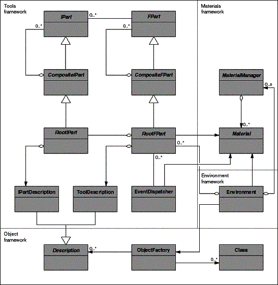
- Figure 7-3: Class model structure of the redesigned Tools
framework.
The framework consists of two primary class hierarchies, the
IPart and the FPart class hierarchy, as well as additional Description
classes and the EventDispatcher class.
An IP object is an instance of (a subclass of) IPart, and an
FP object is an instance of (a subclass of) FPart.
The redesigned framework now employs the class-based version
of the Composite design pattern [GHJV95], so there are subclasses
CompositeIPart and CompositeFPart of classes IPart and FPart,
respectively. This is the only major structural change to the
framework. Effectively, it is a refactoring of functionality among
the classes rather than the introduction of new functionality.
Any leaf IP or FP object must be an instance of a subclass
of IPart or FPart, respectively, but not of CompositeIPart or
CompositeFPart. Any IP or FP object that may contain sub-IPs or
sub-FPs must be an instance of a subclass of CompositeIPart or
CompositeFPart. If, in addition, an IP or FP object serves as
the root of the IP or FP object hierarchy, it must be an instance
of a subclass of RootIPart or RootFPart.
The RootIPart and RootFPart classes provide clients with instances
of IPartDescription and ToolDescription, respectively. These description
classes identify a specific subclass of RootIPart or RootFPart.
They are subclasses of a more generalized Description class, which
stems from the Object framework. A ToolDescription identifies
the tool by its root-FP class for a given tool name, and an IPartDescription
identifies the root-IP class for a given root-FP class.
7.4.2 Class model
The Tools framework comprises the IPart, CompositeIPart, and
RootIPart classes, the FPart, CompositeFPart, and RootFPart classes,
the IPartDescription and the ToolDescription classes, and the
EventDispatcher class.
The FPart class hierarchy defines the abstract classes for
building the FP objects of a software tool instance. It is structured
according to the class-based version of the Composite pattern.
Leaf-FP classes must inherit from FPart (but not from CompositeFPart),
Composite-FP classes that are not root-FP classes must inherit
from CompositeFPart, and Root-FP classes must inherit from RootFPart.
- FPart is the abstract superclass of all FP objects in a tool.
It provides role types that define what clients can do with any
kind of FP object. For example, FP objects collaborate with their
super-FP in the FP object hierarchy and they collaborate with
their IP objects.
- CompositeFPart is the abstract superclass of all FP objects
in a tool that may have sub-FP objects. It is a subclass of FPart.
In addition to the role types inherited from FPart, it provides
role types of role models that create, manage and collaborate
with sub-FP objects.
- RootFPart is the abstract superclass of all root-FP objects.
In addition to the role types inherited from CompositeFPart,
it provides role types that define how a root-FP object collaborates
with its environment.
The IPart hierarchy provides the abstract classes for IP objects
of a tool instance. It is structured ismorphically to the FPart
hierarchy, employing the Composite pattern again. Leaf-IP classes
must inherit from IPart, composite-IP classes must inherit from
CompositeIPart, and root-IP classes must inherit from RootIPart.
- IPart is the abstract superclass of all IP classes. It provides
role types that define what clients can do with any kind IP object.
This includes the collaboration with its super-IP, as well as
the collaboration with its FP object.
- CompositeIPart is the abstract superclass of all IP objects
that may have sub-IP objects. It is a subclass of IPart, to the
role type set of which it adds role types for creating, managing,
and collaborating with sub-IP objects in the hierarchy.
- RootIPart is the abstract superclass of all root-IP classes.
It is a subclass of CompositeIPart, to the role type set of which
it adds role types for collaborating with its FP object.
Software tools are instantiated by creating the root-FP object,
which then builds the rest of the tool. The root-FP object may
either be instantiated directly by naming its class, or it may
be instantiated lazily by using a name reserved for the tool (for
example, "Customer Browser" or "Risk Assessment
Tool"). The lazy instantiation process uses the Product Trader
pattern. This pattern is used twice, for the root-FP and for the
root-IP. The specifications for these classes are subclasses of
Description, which is a class inherited from the Object framework.
- ToolDescription is a concrete subclass of Description. Every
concrete root-FP class provides an instance of ToolDescription
that offers a tool-specific key object for use in a dictionary.
The key is calculated from a string that represents the tool
name. In this context, the key used to identify an FP class in
the Object Factory.
- IPartDescription is a concrete subclass of Description. Every
concrete root-IP class provides an instance of IPartDescription
that offers a root-IP specific key object for use in a dictionary.
The key is an identifier for the FP class the root-IP class can
work with (the IP class must match the FP class). IP root classes
are registered under this key in the object factory.
Finally, software tools coordinate each other using a central
event dispatcher.
- EventDispatcher is a concrete class that is instantiated
as the event dispatcher singleton. Tools use it to communicate
state changes to other tools. The communication is based on a
fixed set of generally known event types, for which tools may
register interest, and about whose concrete occurrences they
are notified.
The root-FP object of each tool can access the event dispatcher
at its central location. Each root-FP registers its interest in
particular other tools or their materials, and provides the dispatcher
with event notifications about changes to its own state or its
materials.
7.4.3 Free role models
The role models of the framework can be classified into free
externally visible role models, and hidden internal role models.
This first part focuses on the free role models, as they are available
to black-box use clients.
The free role models fall into two categories.
- Managing a tool through its FP objects. These are role models
that describe how root-FP objects communicate with their environment.
- Creating a tool using the Product Trader pattern. These role
models describe how description objects are created to instantiate
the root-IP and FP object of a tool without naming their classes.
Figure 7-4 shows the class model including all free and all
internal role models.
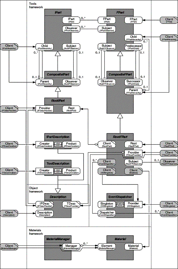
- Figure 7-4: Class model of the redesigned Tools framework,
including all role models.
The following role models deal with managing a tool through
its FP objects.
- The FPart role model serves to provide functionality that
is available from any FP object for any Client. FPart provides
the FPart role type, and Client is a free role type. The FPart
role type provides all needed information about the FP object,
for example its name (for resource management).
- The RootFPart role model serves to provide functionality
to clients, which is available from any root-FP object. A Client
thereby handles the RootFPart. RootFPart provides the RootFPart
role type, and Client is a free role type.
The RootFPart role type lets clients get and set the main
material of the tool, request status information about the tool,
and start it up or shut it down.
- The RootFPObserver role model serves to let exactly one framework-external
object monitor a root-FP object for state changes. It is an instance
of the Observer pattern. RootFPart provides the Subject role,
and Observer is a free role type.
The Subject role type provides operations to register and
unregister the Observer object. The Observer object provides
operations to receive the state change notifications.
The following role models deal with instantiating a tool. The
Description role model is defined in the Object framework. It
is described here to help understand the application of the Product
Trader pattern.
- The Description role model serves to match Description objects
with each other and to maintain them in a dictionary. Each Description
object identifies a specific object (typically a class). The
role model is an instantiation of the Specification patterns
from [Rie96c, EF97]. Description provides the Description role
type, and Client is a free role type.
The Description role type provides operations that return
a key that identifies the Description object. Two keys received
from two different Description objects are equal, if they represent
the same class. In addition, the Description role type provides
operations to match two different Description objects and check
for substitutability.
Subclasses of Description implement how to compute the key,
check for equality, and match two Description objects. Example
subclasses are ToolDescription and IPartDescription.
- The TDescProvider role model (ToolDescriptionProvider) makes
a root-FP class object provide a Description object that unambiguously
identifies the class. RootFPart provides the Provider role type,
Description provides the Description role type, and Client is
a free role type.
Any concrete subclass of RootFPart instantiates exactly one
ToolDescription object. The root-FP class object returns this
Description object when asked for it through the Provider role
type. For the creation of the ToolDescription object, the concrete
RootFPart subclass uses the TDescCreation role model.
- The TDescCreation role model (ToolDescriptionCreation) serves
to instantiate a ToolDescription object with sufficient parameters
to identify the object the Description object represents. It
is shown in the figure using the object creation shorthand. ToolDescription
provides the class-level Creator role type and the instance-level
Product role type, and Client is a free role type.
The Creator role type offers instantiation operations that
take a string. The string represents the tool name.
This role model is used by the environment of the Tools framework
to instantiate a tool using its name only (rather than a specific
class name).
- The IPDescProvider role model (IPartDescriptionProvider)
makes a root-IP class object provide a Description object that
unambiguously identifies the class. RootIPart provides the Provider
role type, Description provides the Description role type, and
Client is a free role type.
Any concrete subclass of RootIPart instantiates exactly one
IPartDescription object. The root-IP class object returns this
Description object when asked for it through the Provider role
type. For the creation of the IPartDescription object, the concrete
RootIPart subclass uses the IPDescCreation role model.
- The IPDescCreation role model (IPartDescriptionCreation)
serves to instantiate an IPartDescription object with sufficient
parameters to identify the object the Description object represents.
It is shown in the figure using the object creation shorthand.
IPartDescription provides the class-level Creator role type and
the instance-level Product role type, and Client is a free role
type.
The Creator role type offers instantiation operations that
take the root-FP class the root-IP class has been designed to
work with.
This role model is used by the environment of the Tools framework
to instantiate the root-IP object for a new tool.
These role models (Description, ToolDescription, TDescProvider,
IPartDescription, IPartProvider) and these classes (Description,
ToolDescription, IPartDescription) taken together with the ObjectFactory
introduced as part of the Environment framework, form the instantiation
of the Product Trader pattern.
7.4.4 Internal role models
The internal role models structure the communication of framework
objects among each other. They fall into four main categories:
- IPart with FPart communication. These role models describe
how the IP objects of a tool collaborate with their respective
FP object.
- Managing the FP object hierarchy. These role models describe
how the FP object hierarchy is built and how the FP objects collaborate
with each other.
- Managing the IP object hierarchy. These role models describe
how the IP object hierarchy is built and how the IP objects collaborate
with each other and with FP objects.
- Maintaining state dependencies between tools. These role
models define how root-FP objects (each representing a specific
tool instance) communicate to maintain their state dependencies.
The following first category of role models describes how IP
objects collaborate with FP objects.
- The FPart role model serves to provide functionality that
is available from any FP object for any Client. FPart provides
the FPart role type, and Client is a free role type. The FPart
role type provides all needed information about the FP object,
for example its name (for resource management).
- The IPart role model serves to let an FP object manage its
IP objects. IP objects can add or remove themselves from an FP,
and the FP can use the standard functionality of an IP, like
showing or hiding it. IPart provides the IPart role type, and
FPart provides the FPart role type.
- The FPartObserver role model serves to make an FP object
notify its IP object about state changes relevant for the handling
and user-interface of the tool component. It is an instance of
the Observer pattern. FPart provides the Subject role type, and
IPart provides the Observer role type.
- The RootIPart role model serves to let a root-FP object handle
the IP object hierarchy as a whole. It provides operations to
startup, show, hide, and shutdown the overall user interface.
RootIPart provides the Root role type, and RootFPart provides
the Client role type.
The following second category of role models describes how
FP objects collaborate with each other to build and maintain the
FP object hierarchy of a tool.
The following third category of role models describes how IP
objects collaborate with each other to build and maintain the
IP object hierarchy of a tool, and how they communicate with FP
objects.
- The IPartHierarchy role model is used to build and change
the IP object hierarchy. It is an instance of the Composite pattern.
IPart provides the Child role type, CompositeIPart provides the
Parent role type, and Client is a free role type. Typically,
the Client role type is picked up by subclasses of CompositeIPart
from a framework extension.
- The SubIPObserver role model serves to make a sub-IP object
notify its parent-IP object about state changes relevant for
the display of the user interface. It is an instance of the Observer
pattern. IPart provides the Subject role type, and CompositeIPart
provides the Observer role type.
Finally, the following fourth category of role models describes
how the root-FP objects communicate to maintain their state dependencies.
- The EventDispatcher role model serves to inform tools about
state changes of other tools or materials they depend on. It
is a variant of the Observer pattern. EventDispatcher provides
the Dispatcher role type, and RootFPart provides the Client role
type.
A Client may act both as a source and as a target of event
notifications. First, a Client registers itself at the Dispatcher,
providing its type (tool type) and name (tool instance). Then,
it registers those materials at the Dispatcher, for which it
holds ownership. It thereby promises to inform the Dispatcher
about state changes of these materials. Finally, it registers
his interest into state changes of other tools or materials using
names or object references to identify them.
At runtime, the Client informs the Dispatcher about relevant
state changes. The Dispatcher dispatches these event notifications
to other Clients that had registered interest in these state
changes.
Therefore, the Dispatcher role type provides operations for
Clients to register their interest in various types of events,
as well as operations to receive and dispatch event notifications.
The Client role type in turn provides operations for the Dispatcher
to call back on it, that is to receive the event notifications.
- The EDSingleton role model serves to provide a convenient
access point to the system-wide EventDispatcher singleton. It
is shown in the figure using the Singleton shorthand. EventDispatcher
provides the class-level Provider role type and the instance-level
Singleton role type, and RootFPart provides the Client role type.
7.4.4.1 Built-on classes
The Tools framework builds on several other frameworks. The
two most important ones are the Widget framework (CommonWidgets
and VisualAge Parts, in this case), and the Materials framework.
- For building the user interface, an IP object arranges a
set of widgets in a hierarchical fashion. How this is done, depends
on the concrete IP class. However, the IPart class itself holds
a reference to a distinguished root Widget for the part of the
user interface the IP is responsible for.
- For handling material objects, a root-FP object maintains
a reference to the main material object the tool is working on.
A material manager object maintains such material objects. Figure
7-4 illustrates these relationships (but does not detail them).
The use of these built-on classes takes place with the appropriate
role models. It would be tedious and tiresome to add them to the
discussion, so they are omitted.
7.5 The new Environment framework
The old Tools framework has been split up into the redesigned
Tools framework and the new Environment framework to better separate
design and implementation artifacts and ease application packaging.
This section describes how parts of the new Environment framework
use the Tools framework.
The Environment framework integrates the Tools framework into
the larger context of a (desktop) application. The Environment
framework provides the root objects of a system. These root objects
control the startup and shutdown of the application process, instantiate
tools, and connect tools with the material management and individual
materials. The focus of this discussion is on the collaboration
of the Environment framework with the Tools framework only. All
issues not relating to this collaboration are omitted.
The focus of the Environment framework is the Environment class,
which is the class that provides the root object the system is
started up by. The Environment object creates, manages, and deletes
all tools. Tools are represented by their root objects, which
are instances of concrete subclasses of RootFPart. Currently,
tools are single-threaded, which allows for the simplified use
of singleton objects.
The environment object uses a system-wide object factory to
instantiate a tool. The object factory is the sole instance of
ObjectFactory. From a client, the factory receives a specification
for an object, determines a class that matches the specification,
and creates an instance of the class, which it returns. A class
specification is always an instance of a concrete subclass of
Description like IPartDescription or ToolDescription.
Description and ObjectFactory are classes from the Object framework.
Their use allows application developers to configure a process
with new tools through configuration data and dynamic class loading,
without having to change and recompile the system.
Figure 7-5 shows the design of Environment framework and its
use of the Tools framework.
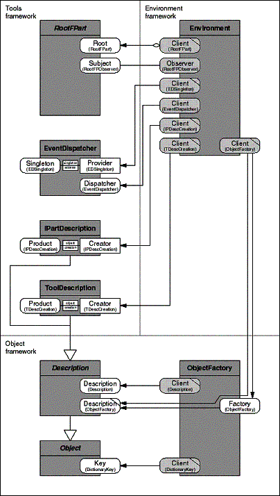
- Figure 7-5: The integration of the Tools framework into an
environment.
Of the 7 role types provided by the Environment class, 6 are
from the Tools framework, where they are discussed (see Section
7.3). These are the RootFPart, RootFPartObserver, IPDescCreation,
TDescCreation, EventDispatcher, and EDSingleton role models.
In addition, the Environment class provides the free client
role type of the Object Factory role model.
For its implementation, the Object Factory uses further role
models from the Object framework.
- The Description role model (from the Object framework) serves
to match specifications with each other. It is an instance of
the Specification pattern [Rie96c, EF97] and part of an instance
of the Product Trader pattern. Description provides the Description
role type, and ObjectFactory provides the Client role type.
- The DictionaryKey role model (from the Object framework)
serves to make an object provide keys (hashcodes) of itself for
use in a dictionary (hashtable). It is an instance of a common
(unnamed) pattern. Object provides the Key role type, and ObjectFactory
provides the Client role type.
There are many more role models, but they do not add much to
showing how the Environment framework is using the Tools framework.
Thus, they are omitted from this discussion.
7.6 Experiences and evaluation
During the redesign process the redesign team made use of role
modeling and the role-model-based design pattern catalog. The
following subsections present the experiences of team members
in a structured way based on the problems motivating this dissertation.
I received these experiences and observations shortly after the
redesign process had been finished and after the new framework
had been released to users.
Of primary interest is the quality of the redesigned framework
and whether it has overcome the problems stated earlier in this
chapter. This is the case. However, while the redesign team used
role modeling for its work, the framework users did not. They
only received traditional documentation. The primary reason for
this is that role modeling as presented in this dissertation requires
framework users and developers to have substantial experience
in object-orientation (see thesis statement in Chapter 2).
In large projects like the KMU Desktop project, the developer
population is diverse, and not everyone can be expected to be
an expert of object-orientation. There are many technical and
organizational solutions to the problems strong variations in
developer expertise cause for framework-based development. Some
of those applied in the KMU Desktop project are listed in Section
7.6.6, which also shortly discusses how the framework kept evolving
after the initial redesign.
7.6.1 Statistics of case study
The KMU Desktop Tools framework provides us with the data shown
in Table 7-1.
|
Number of classes |
9 |
|
Number of role models |
17 |
|
Number of pattern instances |
10 |
|
Number of role types assigned to classes |
31 |
|
Ratio of role types per class |
3.44 |
|
Standard deviation of role types per class |
1.77 |
|
Ratio of role models per class |
1.89 |
|
Ratio of pattern instances per role model |
0.59 |
Table 7-1: Raw data and computed figures from the Tools framework. The KMU Desktop Object framework provides us with the data shown in Table 7-2.
|
Number of classes |
3 |
|
Number of role models |
3 |
|
Number of pattern instances |
2 |
|
Number of role types assigned to classes |
6 |
|
Ratio of role types per class |
2.0 |
|
Standard deviation of role types per class |
0.82 |
|
Ratio of role models per class |
1.0 |
|
Ratio of pattern instances per role model |
0.67 |
Table 7-2: Raw data and computed figures from the Object framework.
The KMU Desktop Environment framework provides us with the
data shown in Table 7-3.
|
Number of classes |
1 |
|
Number of role models |
0 |
|
Number of pattern instances |
0 |
|
Number of role types assigned to classes |
7 |
|
Ratio of role types per class |
7.0 |
|
Standard deviation of role types per class |
0 |
|
Ratio of role models per class |
0 |
|
Ratio of pattern instances per role model |
N/A. |
Table 7-3: Raw data and computed figures from the Environment
framework.
The discussion of the frameworks only shows their key interface
architecture and omits classes of lesser importance and helper
classes. Also, it does not show any extension. Finally, the Environment
framework is shown only in so far as it relates to the Tools framework.
7.6.2 Complexity of classes
Regarding the complexity of classes, the redesign team made
the following observations:
- Designing classes. Team members found that the focus on role
types and role models made designing the new classes easier than
the original process (as it was remembered).
- Learning classes. Framework users and original developers
said that they could more easily understand the new classes than
they were able to understand the original ones.
- Using classes. Also, the users of the new framework said
that the redesigned framework was easier to use than the original
framework.
The use of Smalltalk method categories helped learning and
using classes. The method categories map directly on role types.
These observations apply to all complex classes. For example,
the RootFPart or Environment classes became easier to define and
work with once they were viewed from the point of view of role
types.
7.6.3 Complexity of object collaboration
Regarding the complexity of object collaboration, the redesign
team made the following observations:
- Designing object collaborations. Team members continuously
switched between a class model structure and an object collaboration
view, the later of which was based on role models.
- Learning object collaboration. Users and original developers
said that they could more easily understand how objects collaborated
to achieve the overall purpose of the framework.
- Using the framework. Users of the new framework said that
the redesigned framework was easier to use than the original
framework, in particular with respect to how the objects interacted.
Smalltalk method categories also supported thinking in terms
of collaborations, because the roles of objects could be distinguished
from each other, and method categories of one class had counterparts
at those classes whose instances were part of the different object
collaboration tasks.
Again, these observations apply to all complex collaborations
between objects. For example, the collaboration between an IP
and an FP object, and the collaboration between a root-FP object
and the environment object became much easier to define and handle
once the different collaboration tasks involved were understood
and modeled using role models.
7.6.4 Clarity of requirements put upon use-clients
Regarding the problems of clear expectations on use-clients
of the framework, no specific observations were made. This is
primarily due to the fixed embedding of the Tools framework into
the Environment framework. The lack of further clients prevents
the repeated use of free role types, and therefore does not suggest
anything with respect to their usefulness in defining requirements
on use clients.
7.6.5 Reuse of experience through design patterns
Finally, the redesign team observed that both the original
and the new framework exhibit a high density of pattern applications.
Hence, it achieved a high degree of reuse of experience.
The Tools framework uses the following patterns: Composite
(both role-model-based and class-based version), Observer (repeatedly),
Chain of Responsibility, Product Trader, and Specification. It
uses further undocumented patterns (keys for a dictionary, Class
Object). Also, the documentation does not show several pattern
instances, in particular those close to the code.
In the new framework, the team was able to view role models
as pattern instances that we had not recognized as such before.
For example, the team's analysis of the collaboration between
a super-FP and a sub-FP lead to the introduction of the FPartObserver
and FPartChain role models, while only one (implicit) role model,
an instance of the Observer pattern, existed in the original framework.
The team made this design decision, because the focus on object
collaboration tasks made it recognize the two different purposes
the original Observer pattern application was being used for.
Other examples are the same distinction on the IPart class
hierarchy side, and the separation of the different collaboration
tasks in the RootFPart interface.
Perhaps the most important example of how role modeling eased
reusing design experience is the application of the Composite
pattern. The original design repeatedly introduced code in subclasses
that reflected the Composite pattern. Once the team recognized
this, it decided to change the class model structure accordingly
to better reflect the class-based version of the Composite pattern.
Disassembling the existing class model into its role model pieces,
refactoring the class model to match the class-based version of
the pattern, and recomposing it was significantly facilitated
through the use of role models.
The use of role modeling made the recognition and application
of design experience in the form of design patterns easier than
would have been possible with a traditional class-based approach.
7.6.6 Further evolution of framework
Since the redesign and its subsequent implementation in March
1998 (and the feedback I got at that time) the framework has kept
evolving. As of April 1999, the following changes have been applied
to the framework.
- Simplification of FPart class hierarchy. The classes FPart
and CompositeFPart have been merged to form one FPart class.
However, the functionality of the classes has remained the same.
In particular, this one FPart class still represents an instance
of the Composite pattern. (See the Composite pattern example
in Section 3.3.11 on design patterns in role modeling).
- Simplification of IPart class hierarchy. Similarly, IPart
and CompositeIPart have been merged to form one IPart class.
In addition, a generic RootIPart class has been introduced that
need not be subclassed anymore.
- Simplification of ObjectFactory. The Description classes
are gone and specifications for classes like FPart or IPart are
handled generically as objects. Strings and class objects now
directly serve as specifications.
- Introduction of support tool. A software tool now supports
the creation of new tools, including both IP and FP classes.
The tool frees users from implementing behavior that cannot be
captured as part of the framework but that is repetitive and
redundant otherwise.
For the case study, it is important to note that the framework
functionality did not change much over the course of its evolution.
The original framework was already close to the redesigned framework
in terms of functionality, and the current version is even closer
to the redesigned framework.
What did change is the class structure and the distribution
of responsibilities among classes. The framework evolved towards
less but more complex classes whose interfaces are highly structured
through method categories. Most of the method categories represent
a specific role type.
The evolution process (disassembling class functionality into
pieces and recomposing them to form a new class structure) represents
further evidence that role types and role models are better at
capturing functionality than single classes.
|
|
|